Cisco IOS IP SLAs can send SNMP traps that are triggered by events such as the following:
• Connection loss
• Timeout
• Round-trip time threshold
• Average jitter threshold
• One-way packet loss
• One-way jitter
• One-way mean opinion score (MOS)
• One-way latency
Alternately, an Cisco IOS IP SLAs threshold violation can trigger another Cisco IOS IP SLAs operation for further analysis.
The Cisco IOS IP SLAs MPLS VPN Awareness feature provides the capability to monitor IP service levels within Multiprotocol Label Switching (MPLS) Virtual Private Networks (VPNs). IP SLAs operations can be configured for a specific VPN by specifying a VPN routing and forwarding (VRF) name.
*************
The IP SLAs UDP jitter operation was primarily designed to diagnose network suitability for real-time traffic applications such as voice over IP (VoIP), video over IP, or real-time conferencing.
UDP jitter operations are capable of measuring the following:
Per-direction jitter (source to destination and destination to source)
Per-direction packet-loss
Per-direction delay (one-way delay)
Round-trip delay (average round-trip time)
Before configuring a UDP jitter operation on the source device, the IP SLAs Responder MUST be enabled on the target device (the operational target). The IP SLAs Responder is available only on Cisco IOS software-based devices.
When compared to the IP SLAs User Datagram Protocol (UDP) jitter operation, the IP SLAs ICMP jitter operation may provide less accurate measurements because the accuracy of the measurements provided by a non-Cisco destination device cannot be determined.
Since ICMP packets do not support voice technology, the IP SLAs ICMP jitter operation does not support Mean Opinion Score (MOS), Calculated Planning Impairment Factor (ICPIF), or estimated transmission rating factor (R) reaction configuration capabilities.
*************
The IP SLAs ICMP Jitter Operation feature provides the following key benefits:
End-to-end performance measurements between a Cisco device (source) and any other IP device (destination) using ICMP.
Proactive threshold violation monitoring through Simple Network Management Protocol (SNMP) trap notifications and syslog messages.
The IP SLAs ICMP jitter operation supports the following statistical measurements:
Jitter (source-to-destination and destination-to-source)
Latency (source-to-destination and destination-to-source)
Round-trip time latency
Packet loss
Successive packet loss
Out-of-sequence packets (source-to-destination, destination-to-source, and round-trip)
Late packets
*************
The IP SLAs UDP echo operation measures end-to-end response time between a Cisco router and devices using IP. UDP is a network layer (Layer 3) Internet protocol that is used for many IP services. UDP echo is used to measure response times and test end-to-end connectivity.
UDP echo accuracy is enhanced by using the IP SLAs Responder at Router A, the
destination Cisco router. If the destination router is a Cisco router, then IP SLAs sends a UDP datagram to any port number that you specified. Using the IP SLAs Responder is OPTIONAL for a UDP echo operation when using Cisco devices.
A UDP echo operation measures round-trip delay times and tests connectivity to Cisco and
non-Cisco devices.
*************
The IP SLAs HTTP operation measures the round-trip time (RTT) between a Cisco device and an HTTP server to retrieve a web page. The HTTP server response time measurements consist of three types:
DNS lookup—RTT taken to perform domain name lookup.
TCP Connect—RTT taken to perform a TCP connection to the HTTP server.
HTTP transaction time—RTT taken to send a request and get a response from the HTTP server. The operation retrieves only the home HTML page.
The DNS operation is performed first and the DNS RTT is measured. Once the domain name is found, a TCP Connect operation to the appropriate HTTP server is performed and the RTT for this operation is measured. The final operation is an HTTP request and the RTT to retrieve the home HTML page from the HTTP server is measured. One other measurement is made and called the time to first byte which measures the time from the start of the TCP Connect operation to the first HTML byte retrieved by the HTTP operation. The total HTTP RTT is a sum of the DNS RTT, the TCP Connect RTT, and the HTTP
RTT.
*************
The IP SLAs TCP Connect operation measures the response time taken to perform a TCP Connect operation between a Cisco router and devices using IP. TCP is a transport layer (Layer 4) Internet protocol that provides reliable full-duplex data transmission. The destination device can be any device using IP or an IP SLAs Responder.
*************
The IP SLAs ICMP Echo operation measures end-to-end response time between a Cisco router and any devices using IP. Response time is computed by measuring the time taken between sending an ICMP Echo request message to the destination and receiving an ICMP Echo reply. This operation does not require the IP SLAs Responder to be enabled.
*************
The IP SLAs ICMP Path Echo operation records statistics for each hop along the path that the IP SLAs operation takes to reach its destination. The ICMP Path Echo operation determines this hop-by-hop response time between a Cisco router and any IP device on the network by discovering the path using the traceroute facility.
The source IP SLAs device uses traceroute to discover the path to the destination IP device.
A ping is then used to measure the response time between the source IP SLAs device and each subsequent hop in the path to the destination IP device. This operation does NOT require the IP SLAs Responder to be enabled.
*************
The IP SLAs ICMP Path Jitter operation provides hop-by-hop jitter, packet loss, and delay measurement statistics in an IP network. The Path Jitter operation functions differently than the standard UDP Jitter operation, which provides total one-way data and total round-trip data.
The ICMP Path Jitter operation can be used a supplement to the standard UDP Jitter operation. For example, results from the UDP Jitter operation may indicate unexpected delays or high jitter values; the ICMP Path Jitter operation could then be used to troubleshoot the network path and determine if traffic is bottlenecking in a particular segment along the transmission path.
The operation first discovers the hop-by-hop IP route from the source to the destination using a traceroute utility, and then uses ICMP echoes to determine the response times, packet loss and approximate jitter values for each hop along the path. The jitter values obtained using the ICMP Path Jitter operation are approximates because ICMP only provides round trip times.
The ICMP Path Jitter operation is NOT supported in the RTTMON MIB; configuration and performance data can only be obtained using the CLI.
The ICMP Path Jitter operation functions by tracing the IP path from a source device to a specified destination device, then sending N number of Echo probes to each hop along the traced path, with a time interval of T milliseconds between each Echo probe. The operation as a whole is repeated at a frequency of once every F seconds. The attributes are user-configurable.
The IP SLAs ICMP Path Jitter operation is ICMP-based. ICMP-based operations can compensate for source processing delay but cannot compensate for target processing delay. For more robust monitoring and verifying, use of the IP SLAs UDP Jitter operation is recommended.
The jitter values obtained using the ICMP Path Jitter operation are approximates because ICMP does not provide the capability to embed processing times on routers in the packet. If the target router does not place ICMP packets as the highest priority, then the router will not respond properly. ICMP performance also can be affected by the configuration of priority queueing on the router and by ping response.
Unlike other IP SLAs operations, the ICMP Path Jitter operation is not supported in the RTTMON MIB. Path Jitter operations can only be configured using the CLI, and statistics can only be returned using CLI show ip sla commands.
In contrast with other IP SLAs operations, the IP SLAs Responder does NOT have to be enabled on either the target device or intermediate devices for Path Jitter operations. However, the operational efficiency may improve if you enable the IP SLAs Responder;
*************
The FTP operation measures the round-trip time (RTT) between a Cisco device and an FTP server to retrieve a file. FTP is an application protocol, part of the Transmission Control Protocol (TCP)/IP protocol stack, used for transferring files between network nodes.
Both active and passive FTP transfer modes are supported. The passive mode is enabled by default. Only the FTP GET (download) operation type is supported. The URL specified for the FTP GET operation must be in one of the following formats:
ftp://username:password@host/filename
ftp://host/filename
If the username and password are not specified, the defaults are anonymous and test, respectively. FTP carries a significant amount of data traffic and can affect the performance of your network. The results of an IP SLAs FTP operation to retrieve a large file can be used to determine the capacity of the network but retrieve large files with caution because the FTP operation will consume more bandwidth. The FTP operation also measures your FTP server performance levels by determining the RTT taken to retrieve a file.
*************
The DNS operation measures the difference between the time taken to send a DNS request and receive a reply. DNS is used in the Internet for translating names of network nodes into addresses. The IP SLAs DNS operation queries for an IP address if you specify a host name, or queries for a host name if you specify an IP address.
*************
The Dynamic Host Configuration Protocol (DHCP) operation measures the round-trip time (RTT) taken to discover a DHCP server and obtain a leased IP address from it. DHCP provides a mechanism for allocating IP addresses dynamically so that addresses can be reused when hosts no longer need them. IP SLAs releases the leased IP address after the operation.
There are two modes for the DHCP operation. By default, the DHCP operation sends discovery packets on every available IP interface on the router. If a specific server is configured on the router, using the ip dhcp-server command, discovery packets are sent only to that DHCP server.
The DHCP operation also measures your DHCP server performance levels by determining the RTT taken to obtain a leased IP address.
A DHCP relay agent is any host that forwards DHCP packets between clients and servers. Relay agents are used to forward requests and replies between clients and servers when they are not on the same physical subnet. Relay agent forwarding is distinct from the normal forwarding of an IP router, where IP packets are switched between networks somewhat transparently. Relay agents receive DHCP messages and then generate a new DHCP message to send out on another interface.
The IP SLAs DHCP operation contains a relay agent information option—Option 82—which is inserted by the DHCP relay agent when forwarding client-originated DHCP packets to a DHCP server. Servers recognizing the relay agent information option may use the information to implement IP address or other parameter assignment policies. The DHCP server echoes the option back verbatim to the relay agent in server-to-client replies, and the relay agent strips the option before forwarding the reply to the client. Option 82 includes three suboptions that convey information known by the relay agent:
circuit-id—identifies the incoming circuit.
remote-id—provides a trusted identifier for a remote high-speed modem.
subnet-mask—identifies the mask of the logical IP subnet from which the relay agent received the client DHCP packet.
This operation does NOT require the IP SLAs responder to be enabled so there
are no tasks to be performed on the destination device.
Prerequisites for Multioperation Scheduling of IP SLAs Operations
Configure the IP SLAs operations before group scheduling those operations.
Determine the IP SLAs operations you want to schedule as a single group.
Identify the network traffic type and the location of your network management station.
Identify the topology and the types of devices in your network.
Decide on the frequency of testing for each operation. Normal scheduling of IP SLAs operations allows you to schedule one operation at a time. If you have large networks with thousands of IP SLAs operations to monitor network performance, normal scheduling (scheduling each operation individually) will be inefficient and time-consuming.
The IP SLAs multiple operations scheduling functionality allows you to schedule multiple IP SLAs operations as a group using the ip sla group schedule command. The following parameters can be configured with this command:
Group operation number—Group configuration or group schedule number of the IP SLAs operation to be scheduled.
Operation ID numbers—A list of IP SLAs operation ID numbers in the scheduled operation group.
Schedule period—Amount of time for which the IP SLAs operation group is scheduled.
Ageout—Amount of time to keep the operation in memory when it is not actively collecting
information. By default, the operation remains in memory indefinitely.
Frequency—Amount of time after which each IP SLAs operation is restarted. When the frequency option is specified, it overwrites the operation frequency of all operations belonging to the group. Note that when the frequency option is not specified, the frequency for each operation is set to the value of the schedule period.
Life—Amount of time the operation actively collects information. The operation can be configured to run indefinitely. By default, the lifetime of an operation is one hour.
Start time—Time when the operation starts collecting information. You can specify an operation to start immediately or at an absolute start time using hours, minutes, seconds, day, and month. The IP SLAs multiple operations scheduling functionality schedules the maximum number of operations possible without aborting. However, this functionality skips those IP SLAs operations that are already running or those that are not configured and hence do not exist. The total number of operations will be calculated based on the number of operations specified in the command, irrespective of the number of operations that are missing or already running. The IP SLAs multiple operations scheduling functionality displays a message showing the number of active and missing operations. However, these messages are displayed only if you schedule operations that are not configured or are already running.
A main benefit for scheduling multiple IP SLAs operations is that the load on the network is reduced by distributing the operations equally over a scheduled period. This distribution helps you to achieve more consistent monitoring coverage. To illustrate this scenario, consider configuring 60 operations to start during the same 1-second interval over a 60-second schedule period.
If a network failure occurs 30 seconds after all 60 operations have started and the network is restored before the operations are due to start again (in another 30 seconds), then this failure would never be detected by any of the 60 operations. However, if the 60 operations are distributed equally at 1-second intervals over a 60-second schedule period, then some of the operations would detect the network failure. Conversely, if a network failure occurs when all 60 operations are active, then all 60 operations would fail, indicating that the failure is possibly more severe than it really is.
Operations of the same type and same frequency should be used for IP SLAs multiple operations scheduling. If you do not specify a frequency, the default frequency will be the same as that of the schedule period. The schedule period is the period of time in which all the specified operations should run.
The following sections explain the IP SLAs multiple operations scheduling process:
Multiple operations scheduling allows you to schedule multiple IP SLAs operations using a single command through the command line interface (CLI) or the CISCO-RTTMON-MIB.
This feature allows you to control the amount of IP SLAs monitoring traffic by scheduling the operations to run at evenly distributed times. You must specify the operation ID numbers to be scheduled and the time range over which all the IP SLAs operations should start. This feature automatically distributes the IP SLAs operations at equal intervals over a specified time frame. The spacing between the operations (start interval) is calculated and the operations are started. This distribution of IP SLAs operations helps minimize the CPU utilization and thereby enhances the scalability of the network.
The IP SLAs Multiple Operations Scheduling feature allows you to schedule multiple IP SLAs
operations as a group using the ip sla group schedule command.
The ip sla group schedule 1 1-10 schedule-period 20 [frequency 20] command is configured. This example schedules operation 1 to operation 10 within operation group 1. Operation group 1 has a schedule period of 20 seconds, which means that all operations in the group will be started at equal intervals within a 20-second period. By default, the frequency is set to the same value as the configured schedule period.
IP SLAs entry configuration commands:
dhcp DHCP Operation
dns DNS Query Operation
ethernet Ethernet Operations
exit Exit Operation Configuration
frame-relay Frame-relay Operation
ftp FTP Operation
http HTTP Operation
icmp-echo ICMP Echo Operation
icmp-jitter ICMP Jitter Operation
mpls MPLS Operation
path-echo Path Discovered ICMP Echo Operation
path-jitter Path Discovered ICMP Jitter Operation
tcp-connect TCP Connect Operation
udp-echo UDP Echo Operation
udp-jitter UDP Jitter Operation
voip Voice Over IP Operation
#ip sla reaction-configuration 1 react ?
jitterAvg Jitter Average in both the directions
jitterDSAvg Jitter Average in the direction from Destination to Source
jitterSDAvg Jitter Average in the direction from Source to Destination
*************
#ip sla reaction-configuration 1 react jitterAvg threshold-type ?
average Average over N attempts
consecutive Consecutive occurrences
immediate React immediately
never Never react
xOfy X out of Y occurrences
*************
#ip sla reaction-configuration 1 react jitterAvg action-type ?
none No action
trapAndTrigger Trap and Trigger action
trapOnly Trap Only action
triggerOnly Trigger Only action
*************
packetLateArrival Packets arriving Late
packetLoss Packet Loss in both direction
packetLossDS Packet Loss in the direction from Destination to Source
packetLossSD Packet Loss in the direction from Source to Destination
packetMIA Missing In Action
packetOutOfSequence Packets arriving out of sequence
IP SLAs Reaction Configuration -
IP SLAs can be configured to react to certain measured network conditions. For example, if IP SLAs measures too much jitter on a connection, IP SLAs can generate a notification to a network management application, or trigger another IP SLAs operation to gather more data.
IP SLAs reaction configuration is performed using the ip sla reaction-configuration command. You can configure the ip sla reaction-configuration command multiple times so as to allow reactions for multiple monitored elements (for example, configuring thresholds for operation 1 for destination-to-source packet loss, and also configuring MOS thresholds for same operation). However, issuing the no ip sla reaction-configuration operation-number will clear all reactions for the specified operation. In other words, disabling of granular reaction elements (no ip sla reaction-configuration operation-number react monitored-element) is not currently supported, so as to provide backwards compatibility with the earlier version of this command.
You can check the configuration of the IP SLAs reaction configuration using the <show ip sla
reaction-configuration> command.
IP SLAs includes the capability for triggering SNMP notifications based on defined thresholds. This allows for proactive monitoring in an environment where IT departments can be alerted to potential network problems, rather than having to manually examine data.
IP SLAs supports threshold monitoring for performance parameters such as average jitter, unidirectional latency and bidirectional round trip time and connectivity. This proactive monitoring capability provides options for configuring reaction thresholds for important VoIP related parameters including unidirectional jitter, unidirectional packet loss, and unidirectional VoIP voice quality scoring (MOS scores).
IP SLAs can generate system logging (syslog) messages when a reaction condition occurs. These system logging messages can then be sent as SNMP notifications (traps) using the CISCO-RTTMON-MIB. For packet loss and jitter, notifications can be generated for violations in either direction (source to destination and destination to source) or for round trip values. Packet loss, jitter and MOS statistics are specific to IP SLAs Jitter operations. Notifications can also be triggered for other events, such as round-trip-time violations, for most IP SLAs monitoring operations.
SNMP notifications (traps) for IP SLAs can be configured as a triggered action, to be sent when monitored values exceed an upper threshold or fall below a lower threshold, or when a set of defined conditions are met. For example, an SNMP trap can be triggered by 5 consecutive timeouts during an IP SLAs operation.
The sending of SNMP traps is one of the options for triggered actions that can be configured for IP SLAs violations. The monitored values (also called monitored elements), the threshold type, and the triggered action are configured using the ip sla reaction-configuration global configuration mode command.
SNMP traps for IP SLAs are supported by the CISCO-RTTMON-MIB and CISCO-SYSLOG-MIB. Use the ip sla logging traps command to enable the generation of SNMP system logging messages specific to IP SLAs trap notifications. Use the snmp-server enable traps rtr command to enable the sending of IP SLAs SNMP trap notifications.
IP SLAs reactions are configured to be triggered when a monitored value exceeds or falls below a specified level, or when a monitored event (such as a timeout or connection loss) occurs. These monitored values and events are called monitored elements.
Round-trip-time (rtt) is one of the monitored values of all IP SLAs operations. Events (such as traps) can be triggered when the rtt value rises above a specified threshold, or when it falls below a specified threshold. To configure rtt as the monitored element, use the following version of the ip sla reaction-configuration command:
Jitter (interpacket delay variance) is one of the monitored values of IP SLAs UDP Jitter operations.
Jitter values are computed as source-to-destination, destination-to-source, and combined round-trip values. Events (such as traps) can be triggered when the average jitter value in either direction, or in both directions, rises above a specified threshold, or when it falls below a specified threshold.
Pactket loss is one of the monitored values of IP SLAs UDP Jitter operations. Jitter values are computed as source-to-destination and destination-to-source values. Events (such as traps) can be triggered when the jitter value in either direction rises above a specified threshold, or when it falls below a specified threshold.
To configure source-to-destination packet loss as the monitored element, use the react PacketLossSD syntax in the ip sla reaction-configuration command.
To configure destination-to-source jitter as the monitored element , use the react PacketLossDS syntax in the ip sla reaction-configuration command.
Mean opinion score (MOS) is one of the monitored values of IP SLAs Jitter VoIP operations. MOS values are computed as numbers to two decimal places, from a value of 1.00 (worst quality) to 5.00 (best quality). Events (such as traps) can be triggered when the MOS value in either direction rises above a specified threshold, or when it falls below a specified threshold.
To configure destination-to-source jitter as the monitored element , use the react mos syntax in the ip sla reaction-configuration command.
The threhold-type syntax of the ip sla reaction-configuration command defines the type of threshold violation (or combination of threshold violations) that will trigger an event. Threshold violation types are as follows:
immediate - Triggers an event immediately when the value for a reaction type (such as response time) exceeds the upper threshold value or falls below the lower threshold value, or when a timeout, connectionLoss, or verifyError event occurs.
consecutive - Triggers an event only after a violation occurs a specified number of times
consecutively. For example, the consecutive violation type could be used to configure an action to occur after a timeout occurs 5 times in a row, or when the round-trip-time exceeds the upper threshold value 5 times in a row
x of y - Triggers an event after some number (x) of violations within some other number (y) of probe operations (x of y)
averaged - Triggers an event when the averaged totals of a value for x number of probe operations exceeds the specied upper-threshold value, or falls below the lower-threshold value. Configuring these threshold violation types is described in the following sections.
Generating Events for Each Violation -
To generate a trap (or trigger another operation) each time a specified condition is met, use the immediate threshold-type keyword:
ip sla reaction-configuration operation-number react data-type threshold-type immediate
threshold-value raising-value falling-value action-type action-value
Generating Events for Consecutive Violations -
To generate a trap (or trigger another operation) after a certain number (x) of consecutive violations, use the consecutive keyword with the optional number-of-occurrences argument:
ip sla reaction-configuration operation-number react reaction-condition threshold-type consecutive [number-of-occurances] threshold-value raising-value falling-value action-type action-value. The default value for number-of-occurances is 5.
Generating Events for x of y Violations -
To generate a trap (or trigger another operation) after some number (x) of violations within some other number (y) of probe operations (x of y), use the xofy [x-value y-value] syntax:
ip sla reaction-configuration operation-number react reaction-condition threshold-type xofy x-value y-value threshold-value raising-value falling-value action-type action-value
The default x-value and y-value is 5 (xofy 5 5).
Generating Events for Averaged Violations -
To generate a trap (or trigger another operation) when the averaged totals of x number of probe operations violate a falling-threshold or rising-threshold, use the average [attempts] syntax:
ip sla reaction-configuration operation-number react reaction-condition threshold-type average [attempts] threshold-value raising-value falling-value action-type action-value
The default value for attempts is 5.
Specifying Reaction Events -
Action type options for the ip sla reaction-configuration command are as follows:
none—No action is taken.
trapOnly - Send an SNMP logging trap when the specified violation type occurs for the monitored element. IP SLAs logging traps are enabled using the ip sla logging traps command. For SNMP logging traps to be sent, SNMP logging must be enabled using the appropriate SNMP commands, including the snmp-server enable traps syslog command.
triggerOnly - Have one or more target operation's operational state make the transition from "pending" to "active" when the violation conditions are met. The target operations to be triggered are specified using the ip sla reaction-trigger command. A target operation will continue until its life expires, as specified by the target operation's configured lifetime value). A triggered target operation must finish its life before it can be triggered again.
trapAndTrigger - Trigger both an SNMP trap and start another IP SLAs operation when the violation conditions are met, as defined in the trapOnly and triggerOnly options above.
In the following example, IP SLAs operation 10 (a UDP Jitter operation) is configured to send an SNM logging trap when the MOS value exceeds 4.9 (best quality) of falls below 2.5 (poor quality)
# ip sla reaction-configuration 10 react mos threshold-type immediate threshold-value 490 250 action-type trapOnly
Thursday, December 30, 2010
Saturday, December 25, 2010
The 3560 Ingress Queue
3560 Ingress Queue (2 Input) -
Inside a DOT1q tag you have COS or Priority Bits - 802.1p ( Layer 2 )
The DSCP value is located in the IP header. ( Layer 3 )
Ingress QoS features such as classification, marking and policing can be configured on a per port basis.
Input map tables and ingress queueing can be configured globally and can not be configured on a per port basis.
You can Classify / Mark the frames based on the incoming CoS / DSCP values or an ACL in one of three ways and only one method per port.

Port based configuration using the mls qos interface based commands.
intf# mls qos cos <#> - This will NOT change the CoS values of a frame that is already tagged, this will only add the CoS value you specify to packets that do not already have a tag.
intf# mls qos cos <#> override - This WILL change the CoS values of ALL frames that are tagged or untagged to the value that you designate.
intf#mls qos extend cos <#> - Will allow you to keep the EF frames from the phone and designate the marking you would like to see attached to the packets received from the PC / Server Ect.
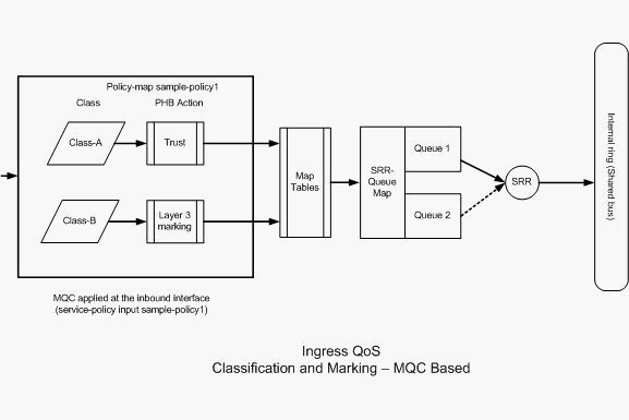
MQC based configuration using class−map and policy−map

NOTE: PHB (Per Hop Behavior)
The configuration under each class of policy−map are called PHB actions. Marking, queuing,
policing, shaping and congestion avoidance are the supported PHB actions in Cisco routers.
Marking and Policing are the ONLY supported PHB actions in the Cisco Catalyst 3560 Switch.
The set and trust commands are Marking PHB actions.
The police command is the Policing PHB action.
Policing can only be configured on the ingress port. Policing can only be configured through MQC and this means there is no interface specific command to police the traffic.
Marking Example:
policy−map Shelby
class Class−A
trust cos
class Class−B
set dscp af21
The Cisco Catalyst 3560 Switch supports only single rate, single bucket policing. This means the switch meters at only one rate and it can profile the traffic in two colors conform and exceed action.

Policing Example:
Policy−map Oscar
class Class−A
police 10000000 8000 exceed−action drop
Policed−dscp map:
0 1 2 3 4 5 6 7 8 9
−−−−−−−−−−−−−−−−−−−−−−−−−−−−−−−−−−−−−−−
0 : 00 01 02 03 04 05 06 07 08 09
1 : 10 11 12 13 14 15 16 17 18 19
2 : 20 21 22 23 24 25 26 27 28 29
3 : 30 31 32 33 34 35 36 37 38 39
4 : 40 41 42 43 44 45 26 47 48 49
5 : 50 51 52 53 54 55 56 57 58 59
6 : 60 61 62 63
mls qos map policed−dscp 46 to 26
Policy−map Abby
class Class−A
trust dscp
police 256000 8000 exceed−action policed−dscp−transmit
SRR for ingress queue can be configured globally.
3 Steps -
i. Queuing
ii. Dropping
iii. Scheduling
Ingress queues use SRR (Shared Round Robin) and is the only mode supported.
The queues share the bandwidth according to configured weights and are guaranteed this amount but not limited to it.
sw1(config)#mls qos srr-queue input ?
bandwidth Configure SRR bandwidth
buffers Configure buffer allocation
cos-map Configure cos-map for a queue id
dscp-map Configure dscp-map for a queue id
priority-queue Configure priority scheduling
threshold Configure queue tail-drop thresholds
Queueing:
buffers Configure buffer allocation
cos-map Configure cos-map for a queue id
dscp-map Configure dscp-map for a queue id
Scheduling:
bandwidth Configure SRR bandwidth
priority-queue Configure priority scheduling
Dropping:
threshold Configure queue tail-drop thresholds
Each queue can support (3) threshold levels, the 3rd is 100% and cant be changed.
On the ingress queue, queue 2 is the priority-queue unlike the output queue where queue 1 is the priority-queue.
Dscp-inputq-threshold map:
d1 :d2 0 1 2 3 4 5 6 7 8 9
------------------------------------------------------------
0 : 01-01 01-01 01-01 01-01 01-01 01-01 01-01 01-01 01-01 01-01
1 : 01-01 01-01 01-01 01-01 01-01 01-01 01-01 01-01 01-01 01-01
2 : 01-01 01-01 01-01 01-01 01-01 01-01 01-01 01-01 01-01 01-01
3 : 01-01 01-01 01-01 01-01 01-01 01-01 01-01 01-01 01-01 01-01
4 : 02-01 02-01 02-01 02-01 02-01 02-01 02-01 02-01 01-01 01-01
5 : 01-01 01-01 01-01 01-01 01-01 01-01 01-01 01-01 01-01 01-01
6 : 01-01 01-01 01-01 01-01
By default as you can see, the DSCP values of 40-46 are place in queue 2.
Queue 2 is the priority queue and is serviced for its configured weight (Default 10%) and the shares the remaining bandwidth 90% between queue 1 AND 2 so 45% each.
There are (3) steps to configure queuing and scheduling.
1. Queue Map configuration -
Maps the packets to 1 of 2 queues based on CoS or DSCP
2. Queue configuration -
Defines the ratio with which to divide the ingress buffers between the (2) queues.
3. Scheduler configuration -
Defines the ratio of the weights that controls the frequency of dequeuing packets from the queues to the stack ring.
This will be a work in progress so hang tight...
Inside a DOT1q tag you have COS or Priority Bits - 802.1p ( Layer 2 )
The DSCP value is located in the IP header. ( Layer 3 )
Ingress QoS features such as classification, marking and policing can be configured on a per port basis.
Input map tables and ingress queueing can be configured globally and can not be configured on a per port basis.
You can Classify / Mark the frames based on the incoming CoS / DSCP values or an ACL in one of three ways and only one method per port.

Port based configuration using the mls qos interface based commands.
intf# mls qos cos <#> - This will NOT change the CoS values of a frame that is already tagged, this will only add the CoS value you specify to packets that do not already have a tag.
intf# mls qos cos <#> override - This WILL change the CoS values of ALL frames that are tagged or untagged to the value that you designate.
intf#mls qos extend cos <#> - Will allow you to keep the EF frames from the phone and designate the marking you would like to see attached to the packets received from the PC / Server Ect.
MQC based configuration using class−map and policy−map
NOTE: PHB (Per Hop Behavior)
The configuration under each class of policy−map are called PHB actions. Marking, queuing,
policing, shaping and congestion avoidance are the supported PHB actions in Cisco routers.
Marking and Policing are the ONLY supported PHB actions in the Cisco Catalyst 3560 Switch.
The set and trust commands are Marking PHB actions.
The police command is the Policing PHB action.
Policing can only be configured on the ingress port. Policing can only be configured through MQC and this means there is no interface specific command to police the traffic.
Marking Example:
policy−map Shelby
class Class−A
trust cos
class Class−B
set dscp af21
The Cisco Catalyst 3560 Switch supports only single rate, single bucket policing. This means the switch meters at only one rate and it can profile the traffic in two colors conform and exceed action.

Policing Example:
Policy−map Oscar
class Class−A
police 10000000 8000 exceed−action drop
Policed−dscp map:
0 1 2 3 4 5 6 7 8 9
−−−−−−−−−−−−−−−−−−−−−−−−−−−−−−−−−−−−−−−
0 : 00 01 02 03 04 05 06 07 08 09
1 : 10 11 12 13 14 15 16 17 18 19
2 : 20 21 22 23 24 25 26 27 28 29
3 : 30 31 32 33 34 35 36 37 38 39
4 : 40 41 42 43 44 45 26 47 48 49
5 : 50 51 52 53 54 55 56 57 58 59
6 : 60 61 62 63
mls qos map policed−dscp 46 to 26
Policy−map Abby
class Class−A
trust dscp
police 256000 8000 exceed−action policed−dscp−transmit
SRR for ingress queue can be configured globally.
3 Steps -
i. Queuing
ii. Dropping
iii. Scheduling
Ingress queues use SRR (Shared Round Robin) and is the only mode supported.
The queues share the bandwidth according to configured weights and are guaranteed this amount but not limited to it.
sw1(config)#mls qos srr-queue input ?
bandwidth Configure SRR bandwidth
buffers Configure buffer allocation
cos-map Configure cos-map for a queue id
dscp-map Configure dscp-map for a queue id
priority-queue Configure priority scheduling
threshold Configure queue tail-drop thresholds
Queueing:
buffers Configure buffer allocation
cos-map Configure cos-map for a queue id
dscp-map Configure dscp-map for a queue id
Scheduling:
bandwidth Configure SRR bandwidth
priority-queue Configure priority scheduling
Dropping:
threshold Configure queue tail-drop thresholds
Each queue can support (3) threshold levels, the 3rd is 100% and cant be changed.
On the ingress queue, queue 2 is the priority-queue unlike the output queue where queue 1 is the priority-queue.
Dscp-inputq-threshold map:
d1 :d2 0 1 2 3 4 5 6 7 8 9
------------------------------------------------------------
0 : 01-01 01-01 01-01 01-01 01-01 01-01 01-01 01-01 01-01 01-01
1 : 01-01 01-01 01-01 01-01 01-01 01-01 01-01 01-01 01-01 01-01
2 : 01-01 01-01 01-01 01-01 01-01 01-01 01-01 01-01 01-01 01-01
3 : 01-01 01-01 01-01 01-01 01-01 01-01 01-01 01-01 01-01 01-01
4 : 02-01 02-01 02-01 02-01 02-01 02-01 02-01 02-01 01-01 01-01
5 : 01-01 01-01 01-01 01-01 01-01 01-01 01-01 01-01 01-01 01-01
6 : 01-01 01-01 01-01 01-01
By default as you can see, the DSCP values of 40-46 are place in queue 2.
Queue 2 is the priority queue and is serviced for its configured weight (Default 10%) and the shares the remaining bandwidth 90% between queue 1 AND 2 so 45% each.
There are (3) steps to configure queuing and scheduling.
1. Queue Map configuration -
Maps the packets to 1 of 2 queues based on CoS or DSCP
2. Queue configuration -
Defines the ratio with which to divide the ingress buffers between the (2) queues.
3. Scheduler configuration -
Defines the ratio of the weights that controls the frequency of dequeuing packets from the queues to the stack ring.
This will be a work in progress so hang tight...
Saturday, December 11, 2010
Nexus Notes ~ Continued
DCNM - Data Center Network management
Configuration Rollback-
This feature enables you to take a snapshot or checkpoint of the current
running configuration and re-apply it at any point without the need to
reload.
3 Types of Configuration rollback
Atomic - Implement only if there are no errors
Best-Effort - Implement a roll back and skip any errors
Stop-at-first-failure - Implement a roll back and stop at the first error.
Limitations-
10 snapshots per VDC
You can not use one snapshot made in one VDC and apply it to the
configuration of another VDC
You can not apply a snapshot in a non-default VDC if there is a change to
the global configuration
Filename 75 characters or less
You can not start the file name with AUTO or SUMMARY
A write erase and reload destroys the snapshot
To change which VDC you are in
#switchto vdc
To create a snapshot
#checkpoint <snapshot-filename>
To rollback to a checkpoint
#rollback running-config checkpoint <snapshot-filename>
If you do not have dual supervisors in the N7k, you cant use the ISSU
VDCs cant be shut down and restarted.
Steps needed to create a VDC and assign resources to it:
Note: VDC(s) are always created from the default admin VDC context (VDC 1)
#vdc <name of VDC>
Allocate interfaces to a VDC
#vdc <name>
#allocate interface ethernet1/17
#show vdc membership
Connectivity Management Processor-
Supports remote management and troubleshooting of the complete system.
This provides complete out-of-band management that is completely
independent independent from the primary OS. It has its own processor,
memory and bootflash and even a separate ethernet management port.
#attach cmp
Friday, December 10, 2010
FCoE (Fiber-Channel over Ethernet)
Fiber-Channel Layers
5 Layers / 0 - 4 (FC0 - FC4)
Layer 0 - Physical Interface
Layer 1 - FC1 Encoding
Layer 2 - FC2 Framing & Flow Control
Layer 3 - FC3 Common Services
Layer 4 - FC4 Protocol Mapping Layer
FCoE (Fiber-Channel over Ethernet)
System MTU 2240 (Default)
Frame size (2112 Bytes) Baby Jumbo
FCoE ether type value 16 bits (0x8906)
____________________
Data Center Enhanced Ethernet
i) Priority Flow Control
Nexus Notes
The Nexus 7000 switch supports 4096 VLANs per Virtual Device Context (VDC) for a system total of ~16k VLANs. Some of these VLANs are used by system-level functions and are not user-configurable.
Bridge Assurance is a new feature that can eliminate issues caused by a malfunctioning bridge. With Bridge Assurance, all ports send and receive BPDUs on all VLANs regardless of their state.
This creates a bidirectional keepalive using BPDUs, and if a bridge stops receiving BPDUs, these ports are placed into an inconsistent state. This functionality can prevent loops that can be introduced as a result of a malfunctioning bridge. Bridge Assurance is enabled by default on any port that is configured with a spanningtree port type network but can be disabled globally with the following command:
(config)# no spanning-tree bridge assurance
To enable Bridge Assurance by setting the spanning-tree port type, enter the following commands:
(config)# int port-channel 1
(config-if)# spanning-tree port type network
An interesting side effect of Bridge Assurance is an automatic pruning function.
In the topology, if a VLAN is defined on but not on , Bridge Assurance puts that VLAN into a blocking state because it is not receiving BPDUs for that VLAN.
(config)# port-profile COMMUNITY1
(config-ppm)# switchport
(config-ppm)# switchport mode access
(config-ppm)# switchport private-vlan host-association 100 102
(config-ppm)# spanning-tree port type edge
(config-ppm)# spanning-tree bpdufilter enable
(config-ppm)# spanning-tree bpduguard enable
(config-ppm)# no shutdown
(config-ppm)# state enabled
(config)# interface ethernet 2/28
(config-if)# inherit port-profile COMMUNITY1
The vPC peer-keepalive link can be either 1 Gbps or 10 Gbps.
vPC peer link:Used to exchange state information between the vPC peers and also provides additional mechanisms that can detect and prevent split-brain scenarios.
Note:The mgmt0 interface can be used as the vPC peer-keepalive link but should be avoided if at all possible.
On the Nexus 7000, the mgmt0 is actually a logical interface representing the physical management port of the active supervisor.
During processes such as supervisor switchover during hardware failure or In-Service Software Upgrades (ISSU), the physical link
supporting the mgmt0 interface might change, causing a disruption of the keepalive messages. By using normal switch interfaces, additionallevels of redundnancy in the port-channels can be used.
If the mgmt0 interface is used as the peer-keepalive link, it is critical to ensure thatall physical management ports are connected to an external device, such as a management switch.
Create VRF for the VPC keepalive link:
(config-if)# vrf context vpc-keepalive
(config)# vrf context vpc-keepalive
(config)# int ethernet 2/47
(config-if)# vrf member vpc-keepalive
(config-if)# ip address 1.1.1.1 255.255.255.252
(config)# interface ethernet 2/48
(config-if)# no switchport
(config-if)# vrf member vpc-keepalive
(config-if)# ip address 1.1.1.2 255.255.255.252
(config-if)# vrf context vpc-keepalive
(config)# vrf context vpc-keepalive
(config)# vpc domain 1
(config-vpc-domain)# peer-keepalive destination 1.1.1.2 source 1.1.1.1 vrf vpckeepalive
(config)# vpc domain 1
(config-vpc-domain)# peer-keepalive destination 1.1.1.1 source 1.1.1.2 vrf vpc-keepalive
(config)# interface port-channel 100
(config-if)# vpc peer-link
Please note that spanning tree port type is changed to “network” port type on vPC peerlink. This will enable spanning tree Bridge Assurance on vPC peer-link provided the STP Bridge Assurance (which is enabled by default) is not disabled.
(config-if)# switchport mode trunk
(config)# interface port-channel 100
(config-if)# vpc peer-link
(config)# interface ethernet 2/1
(config-if)# channel-group 1 mode active
(config)# interface port-channel 1
(config-if)# switchport
(config-if)# switchport mode trunk
(config-if)# vpc 1
VPC Peer-Gateway
This feature is designed to enable certain storage, application servers or load balancers to implement fast-path functionality.
This causes nodes to send return traffic to a specific MAC address of the sender rather than HSRP address.
By default, this traffic might be dropped as VPC loop avoidance does not allow traffic received on a VPC peer-link to be forwarded out a VPC interface (loop avoidance).
A VPC Peer-Gateway enables the VPC peer device to forward packets destined for its peer router MAC locally. To enable the peer-gateway, enter the following command:
(config-vpc-domain)# peer-gateway
(config)# power redundancy-mode ?
combined Configure power supply redundancy mode as combined
insrc-redundant Configure power supply redundancy mode as grid/AC input source redundant
vPC Concepts
The following list defines critical vPC concepts:
vPC: vPC refers to the combined PortChannel between the vPC peer devices and the downstream device.
vPC peer switch: The vPC peer switch is one of a pair of switches that are connected to the special PortChannel known as the vPC peer link. One device will be selected as the primary device, and the other will be the secondary device.
vPC peer link: The vPC peer link is the link used to synchronize states between the vPC peer devices. The vPC peer link carries control traffic between two vPC switches and also multicast, broadcast data traffic. In some link failure scenarios, it also carries unicast traffic. You should have at least two 10 Gigabit Ethernet interfaces for peer links.
vPC domain: This domain includes both vPC peer devices, the vPC peer keepalive link, and all the PortChannels in the vPC connected to the downstream devices. It is also associated with the configuration mode that you must use to assign vPC global parameters.
vPC peer keepalive link: The peer keepalive link monitors the vitality of a vPC peer switch. The peer keepalive link sends periodic keepalive messages between vPC peer devices. The vPC peer keepalive link can be a management interface or switched virtual interface (SVI). No data or synchronization traffic moves over the vPC peer keepalive link; the only traffic on this link is a message that indicates that the originating switch is operating and running vPC.
vPC member port: vPC member ports are interfaces that belong to the vPCs.
Sunday, December 5, 2010
Misc Stuff
debug inter fa 0/0 ==> This enters into just debugging this interface
debug eigrp packet ==> This is the debug you want to see on the command above!
** undebug all
** undebug inter fa 0/0
debug ip error ==> This will tell you all the error's you are getting on anything.
Example: BGP peering, if the neighbors wont peer it will tell you its a hop count issue!
show ip traffic
*Feb 26 15:10:42.235: %OSPF-4-FLOOD_WAR: Process 1 re-originates LSA ID 141.34.25.0 type-3 adv-rtr 141.34.200.1 in area 0
This happens if there are 2 routers with the same router ID!!
______________________
UDLD, like Loop Guard, is used to prevent loops due to unidirectional links. The difference between the features is that Loop Guard uses STP BPDUs to detect these failures, while UDLD uses its own keepalive. UDLD is a Cisco proprietary feature in which peers discover each other by exchanging frames sent to the well-known MAC address 01:00:0C:CC:CC:CC
In "Normal" mode if the physical state of port (as reported by Layer 1) is still up UDLD marks this port as "Undetermined", but does NOT shut down or disable the port, and it continues to operate under its current STP status. This mode of operation is informational and potentially less disruptive (though it does not prevent STP loops).
If UDLD is set to "Aggressive" mode, once the switch loses its neighbor it actively tries to re-establish the relationship by sending a UDLD frames 8 times every 1 second. If the neighbor does not respond after that the port is considered to be unidirectional and sent to err-disable state.
______________________
access-list 1 permit 1.1.1.0 0.0.254.255
R 1.1.1.0 [120/1] via 10.1.1.1, 00:00:03, FastEthernet0/0
R 1.1.3.0 [120/1] via 10.1.1.1, 00:00:03, FastEthernet0/0
R 1.1.5.0 [120/1] via 10.1.1.1, 00:00:03, FastEthernet0/0
access-list 1 permit 1.1.0.0 0.0.254.255
R 1.1.2.0 [120/1] via 10.1.1.1, 00:00:00, FastEthernet0/0
R 1.1.4.0 [120/1] via 10.1.1.1, 00:00:00, FastEthernet0/0
R 1.1.6.0 [120/1] via 10.1.1.1, 00:00:00, FastEthernet0/0
______________________
You must nave AAA new-model turned on for this option to be available.
R1(config)#radius-server local
R1(config-radsrv)#?
Local RADIUS server configuration commands:
authentication supported authentication
eapfast EAP-FAST configurations
exit Exit from local radius server sub mode
group Configure client groups
nas Configure allowed Network Access Servers
no Negate a command or set its defaults
user Configure client usernames and passwords
R1(config-radsrv)#
You can configure a router as a "RADIUS-SERVER" and not just point it to one! It seems like a great way to test if your radius configuration is working without having a real radius server to point to!
______________________
- BPDU Guard > Used to enforce access layer security, when an erroneous BPDU is received on an access interface, by transitioning the interface to shutdown and err-disable state. > Err-disable recovery can be configured to bring the interface out of err-disable state automatically after configured interval. > The err-disable state can be seen with "sh interface status" > Configured globally with "spanning-tree portfast bpduguard default" > Interface configuration "spanning-tree bpduguard enable"
- BPDU Filter > Drops all inbound BDPU's and does not send BDPU's out of the interface. > Unlike BPDU guard, the interface does not go into err-disable state when violation occurs. > Other user traffic will still be forwarded. > If BPDU filter default is enabled with portfast, all interface will run in portfast mode except those which are receiving BPDU's. > Configured globally with "spanning-tree portfast bpdufilter default" > Interface configuration "spanning-tree bpdufilter enable"
- ROOT Guard > Similar to BDPU guard, but the difference is a root guard interface is only disabled if a superior BPDU is received,
placing the interface into ROOT_INCONSISTANT_STATE. > It should be enabled on a downstream interface, which should never become a root-port. > A superior BPDU indicates a better cost to the root bridge, than what is currently installed. > Interface configuration "spanning-tree guard root"
- LOOP Guard > Is used to prevent STP loops from occurring due to a unidirectional link. > Similar to UDLD but instead uses BDPU keepalive to determine unidirectional traffic. > If a blocked port transitions to forwarding state erroneously, a loop can occur. > Blocked ports will be transitioned into LOOP_INCONSISTANT_STATE to avoid loops. > Interface configuration "spanning-tree guard loop"
PPPoE (Point to Point Protocol Over Ethernet)
username R2 password pppoe-lab
int f0/0
pppoe-client dial-pool-number 1
int dialer 1
dialer-group 1
dialer pool 1
encapsulation ppp
ppp authentication chap
ip address dhcp
__________________________
username R1 password pppoe-lab
ip dhcp pool R1
network 192.168.1.0 /24
exit
interface virtual-template 1
ip address 192.168.1.2 255.255.255.0
encap ppp
ppp authentication chap
exit
bba-group pppoe global
virtual-template 1
int f0/0
pppoe enable group global
int f0/0
pppoe-client dial-pool-number 1
int dialer 1
dialer-group 1
dialer pool 1
encapsulation ppp
ppp authentication chap
ip address dhcp
__________________________
username R1 password pppoe-lab
ip dhcp pool R1
network 192.168.1.0 /24
exit
interface virtual-template 1
ip address 192.168.1.2 255.255.255.0
encap ppp
ppp authentication chap
exit
bba-group pppoe global
virtual-template 1
int f0/0
pppoe enable group global
PPP Host Routes
The output of the show ip route command might differ between PPP and HDLC encapsulations when IP unnumbered configuration is used on serial interfaces. PPP installs a host route to the IP address that is used on the serial interface at the other end as a directly connected network. If the same prefix is also learned through OSPF as in this configuration, it displays only as a connected route. This is because connected routes have a lower administrative distance than OSPF and are more preferred. You can change this behavior when you issue the "no peer neighbor-route" command under the serial interfaces which prevents a host route from being installed and treats it as an OSPF route.
This is not the case with HDLC because it does not install a host route. HDLC installs an OSPF route for the address on the other end when IP unnumbered is used.
Frame-Relay Traffic Shaping & Compression
Frame-Relay Traffic Shaping
interface ser 0/0/0
frame-relay traffic-shaping
frame-relay class "name"
frame-relay interface-dlci xxx
class "name"
map-class frame-relay "name"
frame-relay cir 64000
frame-relay mincir 32000
policy-map "name"
shape average "cir" "bc" "be"
shape adaptive "mincer"
map-class frame-relay "name"
service-policy output "name"
frame-relay interface-dlci xxx
class "name"
Frame-Relay Fragmentation
interface ser 0/0/0
frame-relay fragment "fragment size" end-to-end
Frame-Relay DE
frame-relay de-list 1 protocol ip gt 1500
frame-relay de-list 1 protocol ip tcp "port 80"
interface ser 0/0/0
frame-relay de-group 1 "dlci"
Frame-Relay Compression
R1(config)#int S0/0.12
R1(configif)#frame-relay payload-compression packet-by-packet
R1(config)#int S0/0.13
R1(configif)# frame-relay map ip 10.1.13.3 103 Cisco payload-compression packet-by-packet
R1(configif)#int S0/0.12
R1(configsubif)#frame-relay payloadcompression frf9 stac
R1(configsubif)#int S0/0.13
R1(configsubif)#frame-relay map ip 10.1.13.3 103 ietf payload-compression frf9 stac
Frame-Relay Header Compression
R1(config)#int S0/0.12
R1(configsubif)#framerelay ip tcp headercompression
R1(configsubif)#int S0/0.13
R1(configsubif)#framerelay map ip 10.1.13.3 103 Cisco tcp headercompression active
R2(config)#int S0/0.21
R2(configsubif)#framerelay ip tcp header-compression passive
R3(config)#int S0/0
R3(configif)#framerelay map ip 10.1.13.1 301 Cisco tcp header-compression passive
interface ser 0/0/0
frame-relay traffic-shaping
frame-relay class "name"
frame-relay interface-dlci xxx
class "name"
map-class frame-relay "name"
frame-relay cir 64000
frame-relay mincir 32000
policy-map "name"
shape average "cir" "bc" "be"
shape adaptive "mincer"
map-class frame-relay "name"
service-policy output "name"
frame-relay interface-dlci xxx
class "name"
Frame-Relay Fragmentation
interface ser 0/0/0
frame-relay fragment "fragment size" end-to-end
Frame-Relay DE
frame-relay de-list 1 protocol ip gt 1500
frame-relay de-list 1 protocol ip tcp "port 80"
interface ser 0/0/0
frame-relay de-group 1 "dlci"
Frame-Relay Compression
R1(config)#int S0/0.12
R1(configif)#frame-relay payload-compression packet-by-packet
R1(config)#int S0/0.13
R1(configif)# frame-relay map ip 10.1.13.3 103 Cisco payload-compression packet-by-packet
R1(configif)#int S0/0.12
R1(configsubif)#frame-relay payloadcompression frf9 stac
R1(configsubif)#int S0/0.13
R1(configsubif)#frame-relay map ip 10.1.13.3 103 ietf payload-compression frf9 stac
Frame-Relay Header Compression
R1(config)#int S0/0.12
R1(configsubif)#framerelay ip tcp headercompression
R1(configsubif)#int S0/0.13
R1(configsubif)#framerelay map ip 10.1.13.3 103 Cisco tcp headercompression active
R2(config)#int S0/0.21
R2(configsubif)#framerelay ip tcp header-compression passive
R3(config)#int S0/0
R3(configif)#framerelay map ip 10.1.13.1 301 Cisco tcp header-compression passive
POS - Packet over SONET
Synchronous Optical Networking (SONET) and Synchronous Digital Hierarchy (SDH)
OC - Optical Carrier
SONET offers an additional basic unit of transmission, the STS-1 (Synchronous Transport Signal 1) or OC-1, operating at 51.84 Mbit/s—exactly one third of an STM-1/STS-3c/OC-3c carrier.
So (3) STS-1 circuits = 155 Meg.
Saturday, December 4, 2010
Lab Notes - Misc 10.20.2010
BGP multipath does not influence the selection of the best path.
#bgp maximum-paths <iBGP , eBGP> #
BGP next-hop trigger delay <#> (5 sec default)
CDP can detect / Duplex Mismatch, Native VLAN Mismatch / VTP domain name Mismatch
To mitigate and enforce root placement:
intf#spanning-tree guard root
Switch QoS:
mls qos
intf#mls qos cos 2
intf#mls qos cos override
intf#mls qos trust device <cisco-phone | cts (cisco telepresence | ip-camera)
On Trunks:
mls qos trust cos
Flash Cards - BGP / MPLS

Ingress LSRs — Ingress LSRs receive a packet that is not labeled yet, insert a label (stack) in front of the packet, and send it on a data link.
Egress LSRs — Egress LSRs receive labeled packets, remove the label(s), and send them on a data link. Ingress and egress LSRs are edge LSRs.
Intermediate LSRs — Intermediate LSRs receive an incoming labeled packet, perform an operation on it, switch the packet, and send the packet on the correct data link.
An LSR can do the three operations: pop, push, or swap.
An LSR that pushes labels onto a packet that was not labeled yet is called an imposing LSR.
An LSR that removes all labels from the labeled packet before switching out the packet is a disposing LSR.
A label switched path (LSP) is a sequence of LSRs that switch a labeled packet through an MPLS network or part of an MPLS network.
The ingress LSR of an LSP is not necessarily the first router to label the packet. The packet might have already been labeled by a preceding LSR. Such a case would be a nested LSP—that is, an LSP inside another LSP.
A Forwarding Equivalence Class (FEC) is a group or flow of packets that are forwarded along the same path and are treated the same with regard to the forwarding treatment. However, not all packets that have the same label belong to the same FEC, because their EXP values might differ; the forwarding treatment could be different, and they could belong to a different FEC.
__________
BGP
To choose an exit point when you have multiple.
access-list 1 per 10.1.1.0 0.0.0.255
Route-Map Oscar
match ip address 1
set ext-community cost 1 1
#neighbor x.x.x.x route-map in
#router bgp 100
distance 150 x.x.x.x (source) x.x.x.x (subnet of source) <1 _ ACL is route to change the distance on>
#router bgp 100
distance bgp <external> <internal> <local>
#router bgp 100
no bgp fast-external failover
advertisement-interval <iBGP> <eBGP>
Route-Reflector Attributes (Optional Non-Transitive)
i. Origin ID - Router ID of the router that originated the prefix.
ii. Cluster ID - RR ID & Clients
iii. Cluster List - Same as the AS_Path (Loop Avoidance), if RR see's it's own ID it will drop the packet.
BGP Neighbor ORF
This has to be done on both sides or this will not work.
#ip prefix-list <name> permit x.x.x.x/x le 32
#neighbor x.x.x.x prefix-list <name> in
#address-family ipv4 unicast
#neighbor x.x.x.x capability orf prefix-list <send | receive | both>
_______
#ip as-path access-list 1 deny ^300$
#ip as-path access-list 1 permit .*
#neighbor x.x.x.x filter-list 1 in
Using an extended ACL to advertise networks - With BGP it is different.
access-list 101 permit (network) (mask) (mask) (mask)
BGP - Part 1
* Note: Outgoing route advertisements directly affect incoming traffic.
* Note: MED is considered a metric so a lower value is better.
Path Attributes
==> 3 _ 2 _ 2 _ 3 <==
1. Origin (WKM)
2. AS_Path(WKM)
3. Next_Hop (WKM)
4. Local_pref (WKD)
5. Atomic_aggregate (WKD)
6. Aggregate (OT)
7. Community (OT)
8. Originator_ID(ONT)
9. MED (ONT)
10. Cluster_List (ONT)
Origin (WKM) -
IGP / EGP / Incomplete
IGP - NLRI was learned from a protocol internal to the AS is gets the highest preference.
EGP - NLRI was learned from the exterior gateway protocol and gets medium preference.
Incomplete - NLRI was learned from some other means which could be redistribution but there is no real way to know how it got there and gets the lowest preference.
AS_Path (WKM)-
This uses a sequence of AS paths through which the NLRI was received. Beginning with the most recent and ending with the originating AS. The BGP router will only prepend its AS if it being advertised to an EBGP neighbor and NOT an iBGP neighbor. This is considered a loop avoidance mechinism.
Next_Hop (WKM) -
Community (OT) -
Internal BGP - TTL of 255
External BGP - TTL of 1
iBGP and IGP Syncronization
BGP does NOT advertise routes that have been learned from other iBGP peers.
BGP Syncronization: Before a route learned from an iBGP neighbor is entered into the routing table or is advertised to a BGP peer, the route must first be known via an IGP.
Confederations:
AS_Path contains (2) additional attributes:
i. AS_CONFED_SEQUENCE ii. AS_CONFED_SET
Route Selection is as follows inside a confederation.
1. EBGP routes are prefered over member AS then iBGP is last.
NEXT_HOP AND MED can be advertised unchanged along with the ability to send local_pref. Usually peering with an eBGP peer, local_pref means nothing.
Neighbor x.x.x.x default-originate is the same as OSPFs default-information-originate-always in that a default is advertised whether the router has a default route or not.
If only the default is to be sent, you must use a route-filter to suppress all more-specific route's.
neighbor x.x.x.x distribute-list 1 out
access-list 1 per 0.0.0.0
access-list 1 deny any
You can run an IGP to run in passive mode on external eBPG interfaces or can redistribute connected interfaces on AS border routers.
(2) Ways to create an aggregate address under BGP
i. Create a static route and advertise it with the network command.
ii. Use the aggregate-address command
ip route 192.168.192.0 255.255.248.0 null 0
Router BGP 1
network 192.168.192.0 mask 255.255.248.0
The route to null 0 is a safe guard should there not be a more specific match in the routing table.
* Note: MED is considered a metric so a lower value is better.
Path Attributes
==> 3 _ 2 _ 2 _ 3 <==
1. Origin (WKM)
2. AS_Path(WKM)
3. Next_Hop (WKM)
4. Local_pref (WKD)
5. Atomic_aggregate (WKD)
6. Aggregate (OT)
7. Community (OT)
8. Originator_ID(ONT)
9. MED (ONT)
10. Cluster_List (ONT)
Origin (WKM) -
IGP / EGP / Incomplete
IGP - NLRI was learned from a protocol internal to the AS is gets the highest preference.
EGP - NLRI was learned from the exterior gateway protocol and gets medium preference.
Incomplete - NLRI was learned from some other means which could be redistribution but there is no real way to know how it got there and gets the lowest preference.
AS_Path (WKM)-
This uses a sequence of AS paths through which the NLRI was received. Beginning with the most recent and ending with the originating AS. The BGP router will only prepend its AS if it being advertised to an EBGP neighbor and NOT an iBGP neighbor. This is considered a loop avoidance mechinism.
Next_Hop (WKM) -
- If the advertising router and receiving router are in different ASs, the next_hop is the IP address of the advertising routers interface.
- If the advertising router and the recieiving router are in the same AS and the NLRI of the update referes to a destination with the same AS, the next_hop is the IP address of the neighbor that advertised the route.
- If the advertising router and the receiving router are internal peers and the NLRI of the update refers to a destination in a different ASm the nest_hop is the IP address of the external peer from which the route was learned.
Community (OT) -
- Identifies a destination as a member of some community of destinations that share one or more common properties.
- The Community attribute is a set of (4) octet values (AA:NN)
- The first (2) are the AS number.
- The second (2) are the administratively defined identifier.
- The default is (NN:AA) which can be changed with " ip bgp-community new-format".
- INTERNET - Doe's not have a value and all routes belong to this community by default.
- NO_EXPORT - Can not be advertised to an EBGP peer or if a confederation is configured, cant be advertised outside of a confederation.
- NO_ADVERTISE - Routes received with this attribute cant be advertised at all.
- LOCAL_AS - Cant be advertised to EBGP peers including peer in other ASs within a Confederation.
Internal BGP - TTL of 255
External BGP - TTL of 1
iBGP and IGP Syncronization
BGP does NOT advertise routes that have been learned from other iBGP peers.
BGP Syncronization: Before a route learned from an iBGP neighbor is entered into the routing table or is advertised to a BGP peer, the route must first be known via an IGP.
Confederations:
AS_Path contains (2) additional attributes:
i. AS_CONFED_SEQUENCE ii. AS_CONFED_SET
Route Selection is as follows inside a confederation.
1. EBGP routes are prefered over member AS then iBGP is last.
NEXT_HOP AND MED can be advertised unchanged along with the ability to send local_pref. Usually peering with an eBGP peer, local_pref means nothing.
Neighbor x.x.x.x default-originate is the same as OSPFs default-information-originate-always in that a default is advertised whether the router has a default route or not.
If only the default is to be sent, you must use a route-filter to suppress all more-specific route's.
neighbor x.x.x.x distribute-list 1 out
access-list 1 per 0.0.0.0
access-list 1 deny any
You can run an IGP to run in passive mode on external eBPG interfaces or can redistribute connected interfaces on AS border routers.
(2) Ways to create an aggregate address under BGP
i. Create a static route and advertise it with the network command.
ii. Use the aggregate-address command
ip route 192.168.192.0 255.255.248.0 null 0
Router BGP 1
network 192.168.192.0 mask 255.255.248.0
The route to null 0 is a safe guard should there not be a more specific match in the routing table.
Multicast - Flash Cards
My flashcards over time have become quite worn and out of order so I will be just adding them with no regards as to what came first, the chicken or the egg.
AutoRP -
ip pim send-rp-announce (Rendezvous Point)
ip pim send-rp-discover (Mapping agent)
#ip pim send-rp-announce loopback 0 scope 2 group-list 1
224.0.1.39 / 40 will only be used with Auto-RP and / or auto-rp listener.
If you have multiple RPs for a group, the HIGHEST IP wins.
If you want to deny a host from joining group:
#access-list 1 deny 224.0.1.40
#intf fastethernet0/0 #ip multicast boundary 1 <1 is the access-list>
BSR -
ip pim rp-canidate (Rendezvous Point)
ip pim bsr-canidate (Mapping agent)
DENSE MODE
Hellos are generated every 30 seconds and sent to 224.0.0.13 with a TTL (1)
(NOTE: The 224 address can be considered Link-Local, thus the TTL of 1)'
Neighbor Interface Uptime/Expires Ver DR
Address Prio/Mode
10.1.13.1 Serial0/2/0 00:16:37/00:01:21 v2 1 / S P
Uptime - How long have they been neighbors.
Expires - 3 1/2 x's the HELLO interval. (The timer starts at 1 Min 45 Sec and decrements to 1:15 )
Ver - Specifies neighbors PIM version
DR Prio - Has no meaning in dense mode unless PIMv1 is being used.
If the priority is identical, the router with the highest IP address is elected the DR.
The letter "S" indicates that this router is state refresh capable with allows it to remain in a "(P)RUNED" state.
These messages are sent every 60 seconds to the ALL PIM Multicast address of 224.0.0.13 TTL 1
Show Command # show ip pim interface fa 0/0 detail
R1(config-if)#do sh ip igmp group
IGMP Connected Group Membership
Group Address Interface Uptime Expires Last Reporter Group Accounted
224.1.1.1 Loopback0 00:00:31 00:02:28 1.1.1.1
224.0.1.40 FastEthernet0/0 02:15:39 00:02:02 10.1.12.1
R1#sh ip pim inter count | B Address
Address Interface FS Mpackets In/Out
10.1.12.1 FastEthernet0/0 * 24/0
1.1.1.1 Loopback0 * 0/0
10.1.13.1 Serial0/1/1 * 0/12
R1#
____________
access-list 1 permit 224.0.0.0 15.255.255.255
#ip igmp immediate-leave group-list 1 <1 is referencing the ACL>
#ip pim send-rp-announce group-list 1 <1 is referencing the ACL>
____________
Announce RP for all groups but will never be RP.
access-list 1 permit host 1.1.1.1
access-list 2 deny any
#ip pim rp-announce-filter rp-list 1 group-list 2 (This needs to be on the mapping agent)
#ip pim spt-threshold 20 group-list 1
(Amount of time it waits before switching over to the Shortest Path Tree, Default is almost immediate.)
____________
RPF- With multicast, the router will check the static mroute table first.
i. TS, ping the interface on the router that is the source of the MC traffic and then compare it to your mroute table and add any routes needed to pass the RPF.
___________
show pim df Shows bidirectional PIM designated forwarder (DF) information
show pim group-map Displays PIM group-to-protocol mapping information
show pim interface Displays PIM interface information
show pim join-prune statistic Shows PIM join/prune information
show pim neighbor Displays PIM neighbor information
show pim range-list Shows PIM range-list information
show pim topology Displays the PIM topology table information
show pim traffic Displays PIM traffic counters
show pim tunnel Lists information about the PIM tunnel interfaces
show igmp groups Displays group membership information
show igmp interface Provides interface IGMP information
show igmp traffic Displays traffic counters
show mroute Displays the contents of the multicast routing table:
_____________________________
debug pim Enables debugging for PIM events
debug pim neighbor Enables debugging of PIM neighbor events
debug pim group group Enables PIM protocol activity debugging for only the matching group
debug pim interface interface Enables debugging of PIM protocol activity for only the specified interface.
debug pim df-election Enables debugging of PIM DF election exchange messages.
debug mrib route [group] Enables debugging of MRIB routing activity
debug mrib client Enables debugging of MRIB client management activity
debug mrib io Enables debugging of MRIB I/O events
debug mrib table Enables debugging of MRIB table management activity
Monday, October 25, 2010
Flash Cards - OSPFv2
OSPF Packet Types (HD_RUA):
Type 1 - Hello / Type 2 - Database Descriptor / Type 3 - Link-State Request / Type 4 - Link-State Update / Type 5 - Link-State Acknowledgment.
OSPF uses protocol 89 - LSA Aging time 30 minutes / Can be changed: timers pacing lsa-group <Time in Minutes>
When you do a show ip ospf database network - The routing bit set means its a good route and in the RIB.
To inject a default route into OSPF, you need to have one configured already. Or you can use the command:
#Router ospf 1
#default-information originate always
If you are peering with non-cisco routers and having trouble. LLS is th ability to exchange vendor specific data within OSPF packets.
#Router ospf 1
#no capability lls (Link-local Signaling (LLS) support)
OR
intf#ip ospf lls disable
___________
P2P Sub-interfaces - Inverse ARP is disabled by default.
To change the default metric:
Router ospf 1
default-metric <#>
The default redistribution metric is <20>
#ip ospf flood-reduction (Sets the DoNotAge bit)
Hide the MPLS network when someone uses a traceroute:
#no mpls propogate-ttl
Router ospf 1
#max-metric router-lsa <on-startup | time | wait-for-bgp>
#redistribute maximum-prefix <#> <Threshold | warning-only>
OSPF Filtering
Type 1-2 LSA - On ABR
#area 1 range 10.1.1.0 255.255.255.0 <default is advertise> <not-advertise | cost>
#distribute-list 1 <route-map> in
Type 3 LSA - On ABR
#area 2 filter-list prefix <name> in
Type 5 - 7 - ASBR
#summary-address 10.1.1.1 255.255.255.0 <not-advertise>
#distribute-list 1 out
IPv6 Tunneling
~ P2P IPv6 Tunnels ~
Manual
Tunnel source / destination should be an IPv4 address.
Tunnel IP should be an IPv6 address.
Tunnel mode IPv6IP
Manual GRE
Tunnel source / destination should be an IPv6 address.
Tunnel IP should be an IPv6 address.
Tunnel Mode GRE IPv6
~ P2MultiPoint IPv6 Tunnels ~
Automatic 6-4
Used for IPv6 Source / Destination over an IPv4 Network.
Sites use 2002::/16 prefix -- Format 2002:border_router_ipv4_address::/48
Tunnel Source IPv4 address / No tunnel destination required
Tunnel IP address is IPv6 address
Tunnel mode IPv6IP 6to4
ipv6 route 2002::/16 tunnel 0
ISATAP (Intra-site automatic tunnel addressing protocol)
You can use any IPv6 address that you desire unlike auto 6-4. Used for transporting IPv6 within a site, not between.
Interface ID is created using EUI-64 address which is embeeded in last 32 bit of the IPv6 address. e.g. mac_add-FFFE-mac_address
Tunnel IPv6 2001:1234::/64 EUI-64
Tunnel mode IPv6IP ISATAP
Need to add "no ipv6 ND ra-suppress" / "no ipv6 nd suppress-ra
Sunday, October 24, 2010
IPv6 OSPF v3 LSA Types
Link State Type field is 16 bits rather than 8 with IPv4.


OSPFv3 removes the prefix advertisement function from router and network LSAs and puts it in the new Intra-Area Prefix LSA and Link LSA
The Router LSA - OSPFv3
This only describes the originating router and it's links to its neighbors. Prefix information is carried in the intra-area prefix LSA
The Network LSA - OSPFv3
Functionally it is identical to the OSPFv2 Network (Type 2 LSA)
The Inter-Area Prefix LSA - OSPFv3
Functionally it is identical to the OSPFv2 Summary (Type 3 LSA)
The Inter-Area Router - OSPFv3
Functionally it is identical to the OSPFv2 ASBR Summary (Type 4 LSA)
The AS-External LSA - OSPFv3
Functionally it is identical to the OSPFv2 AS External (Type 5 LSA) except for:

The Link LSA - OSPFv3
The link LSA is used for communicating information that is significant only to two directly connected neighbors. A separate link LSA is originated on each if a routers attached links belonging to an OSPFv3 domain.
The Intra-Area Prefix LSA - OSPFv3
MPLS - LDP
MPLS Label Protocol - LDP
MPLS ldp router-id - Best to set it as the IP must be reachable as it is used in the transport addresss in the LDP discovery hello messages.
#mpls label protocol ldp
#mpls label router-id loopback0 <force>
#mpls label range 100 200
Once you enable #mpls ip on an interface, the LSR will attempt to discover neighbors using hello messages that are sourced from UDP 646 224.0.0.2 every 5 seconds (Hold time 15 sec)
2.2.2.2:0 The zero is a 2 Byte value and indicates that its platform wide and anything other than zero indicates that its per-interface.
#show mpls ldp neighbor
There are (2) types of neighbor discovery: i. Basic ii. Extended
Basic- Sends a discover message out every interface in which mpls ip is enabled.
Extended- Sends discover messages to non-directly connected LDP neighbors.
#show mpls ldp discovery all
#show mpls ldp discovery detail
#show mpls ldp parameters
#mpls ldp discovery hello holdtime 45
#mpls ldp discovery hello interval 15
#mpls ldp holdtime 90 <This will change the keep-alive time auto-magically>
This shows the routers <LIB>
#show mpls ldp binding <6.6.6.6>
This shows the <LFIB>
#show mpls forwarding-table <6.6.6.6>
This shows the <FIB>
#show ip cef 6.6.6.6


To configure a router as a PHP:
#mpls ldp explicit-null
#intf fa0/0 - mpls ip


MPLS ldp router-id - Best to set it as the IP must be reachable as it is used in the transport addresss in the LDP discovery hello messages.
#mpls label protocol ldp
#mpls label router-id loopback0 <force>
#mpls label range 100 200
Once you enable #mpls ip on an interface, the LSR will attempt to discover neighbors using hello messages that are sourced from UDP 646 224.0.0.2 every 5 seconds (Hold time 15 sec)
2.2.2.2:0 The zero is a 2 Byte value and indicates that its platform wide and anything other than zero indicates that its per-interface.
#show mpls ldp neighbor
There are (2) types of neighbor discovery: i. Basic ii. Extended
Basic- Sends a discover message out every interface in which mpls ip is enabled.
Extended- Sends discover messages to non-directly connected LDP neighbors.
#show mpls ldp discovery all
#show mpls ldp discovery detail
#show mpls ldp parameters
#mpls ldp discovery hello holdtime 45
#mpls ldp discovery hello interval 15
#mpls ldp holdtime 90 <This will change the keep-alive time auto-magically>
This shows the routers <LIB>
#show mpls ldp binding <6.6.6.6>
This shows the <LFIB>
#show mpls forwarding-table <6.6.6.6>
This shows the <FIB>
#show ip cef 6.6.6.6
To configure a router as a PHP:
#mpls ldp explicit-null
#intf fa0/0 - mpls ip
To stop advertising labels all together:
#no mpls ldp advertise-labels
QoS
A source is on v100 generating 10 UDP PPS, the packet size is 1024 Bytes and is destined for v20 of switch 1 UDP port 5011.
Limit the traffic to 8000b/s, excess should be dropped and set the DSCP value to 18.
HEIRARCHIAL POLICY MAP-
Level 1 affects the SVI traffic and Level 2 affects interface level traffic.
mls qos
class-map cm-interfaces (Child)
match input-interface fastethernet 0/10
!
class-map udp-5011 (Child)
match access-group 101
!
policy-map pm-interfaces (Child)
class cm-interfaces
police 8000 8000 exceed-action drop
!
polcy-map pm-vlan100 (Parent)
class udp-5011
set dscp af21
service-policy pm-interfaces
!
interface fastethernet 0/10
mls qos vlan-based
!
interface vlan100
service-policy input pm-vlan100
__________
Monday, October 18, 2010
BGP - Part 2
If you are going to use "clear ip bgp x.x.x.x soft in / out" you must enable the ability first.
Router BGP 1
neighbor x.x.x.x soft-reconfiguration in
Route-Filtering 101
access-list 1 deny 3.3.3.0 0.0.0.255
access-list 1 permit any
Router bgp 1
neighbor x.x.x.x distribute-list 1 in
(Note: If you have more than (1) BGP neighbor that you can learn this prefix from, then you need to add it to all neighbors.
_________
ip prefix-list oscar deny 3.3.3.0/24
ip prefix-list oscar permit 0.0.0.0/0 le 32
Router bgp 1
neighbor x.x.x.x prefix-list oscar in
(Note: If you have more than (1) BGP neighbor that you can learn this prefix from, then you need to add it to all neighbors.
________
access-list 1 deny 3.3.3.0 0.0.0.255
access-list 1 permit any
Route-map oscar permit 10
match ip address 1
Route-map oscar permit 20
Router bgp 1
neighbor x.x.x.x route-map oscar in
(Note: If you have more than (1) BGP neighbor that you can learn this prefix from, then you need to add it to all neighbors.)
You can also use a DENY route-map and a PERMIT route-map instead.
________
Filtering route's by telling the eBGP neighbor to not send them in the first place.
Router BGP 1
address-family ipv4
neighbor 10.1.23.2 capability orf prefix-list both
ip prefix-list oscar deny 3.3.3.0/24
ip prefix-list oscar permit 0.0.0.0/0 le 32
(Note: If you have more than (1) BGP neighbor that you can learn this prefix from, then you need to add it to all neighbors.)
________
Router BGP 1
neighbor x.x.x.x soft-reconfiguration in
Route-Filtering 101
access-list 1 deny 3.3.3.0 0.0.0.255
access-list 1 permit any
Router bgp 1
neighbor x.x.x.x distribute-list 1 in
(Note: If you have more than (1) BGP neighbor that you can learn this prefix from, then you need to add it to all neighbors.
_________
ip prefix-list oscar deny 3.3.3.0/24
ip prefix-list oscar permit 0.0.0.0/0 le 32
Router bgp 1
neighbor x.x.x.x prefix-list oscar in
(Note: If you have more than (1) BGP neighbor that you can learn this prefix from, then you need to add it to all neighbors.
________
access-list 1 deny 3.3.3.0 0.0.0.255
access-list 1 permit any
Route-map oscar permit 10
match ip address 1
Route-map oscar permit 20
Router bgp 1
neighbor x.x.x.x route-map oscar in
(Note: If you have more than (1) BGP neighbor that you can learn this prefix from, then you need to add it to all neighbors.)
You can also use a DENY route-map and a PERMIT route-map instead.
________
Filtering route's by telling the eBGP neighbor to not send them in the first place.
Router BGP 1
address-family ipv4
neighbor 10.1.23.2 capability orf prefix-list both
ip prefix-list oscar deny 3.3.3.0/24
ip prefix-list oscar permit 0.0.0.0/0 le 32
(Note: If you have more than (1) BGP neighbor that you can learn this prefix from, then you need to add it to all neighbors.)
________
BGP - Part 1
* Note: Outgoing route advertisements directly affect incoming traffic.
* Note: MED is considered a metric so a lower value is better.
Path Attributes
==> 3 _ 2 _ 2 _ 3 <==
1. Origin (WKM)
2. AS_Path(WKM)
3. Next_Hop (WKM)
4. Local_pref (WKD)
5. Atomic_aggregate (WKD)
6. Aggregate (OT)
7. Community (OT)
8. Originator_ID(ONT)
9. MED (ONT)
10. Cluster_List (ONT)
Origin (WKM) -
IGP / EGP / Incomplete
IGP - NLRI was learned from a protocol internal to the AS is gets the highest preference.
EGP - NLRI was learned from the exterior gateway protocol and gets medium preference.
Incomplete - NLRI was learned from some other means which could be redistribution but there is no real way to know how it got there and gets the lowest preference.
AS_Path (WKM)-
This uses a sequence of AS paths through which the NLRI was received. Beginning with the most recent and ending with the originating AS. The BGP router will only prepend its AS if it being advertised to an EBGP neighbor and NOT an iBGP neighbor. This is considered a loop avoidance mechinism.
Next_Hop (WKM) -
Community (OT) -
Internal BGP - TTL of 255
External BGP - TTL of 1
iBGP and IGP Syncronization
BGP does NOT advertise routes that have been learned from other iBGP peers.
BGP Syncronization: Before a route learned from an iBGP neighbor is entered into the routing table or is advertised to a BGP peer, the route must first be known via an IGP.
Confederations:
AS_Path contains (2) additional attributes:
i. AS_CONFED_SEQUENCE ii. AS_CONFED_SET
Route Selection is as follows inside a confederation.
1. EBGP routes are prefered over member AS then iBGP is last.
NEXT_HOP AND MED can be advertised unchanged along with the ability to send local_pref. Usually peering with an eBGP peer, local_pref means nothing.
Neighbor x.x.x.x default-originate is the same as OSPFs default-information-originate-always in that a default is advertised whether the router has a default route or not.
If only the default is to be sent, you must use a route-filter to suppress all more-specific route's.
neighbor x.x.x.x distribute-list 1 out
access-list 1 per 0.0.0.0
access-list 1 deny any
You can run an IGP to run in passive mode on external eBPG interfaces or can redistribute connected interfaces on AS border routers.
(2) Ways to create an aggregate address under BGP
i. Create a static route and advertise it with the network command.
ii. Use the aggregate-address command
ip route 192.168.192.0 255.255.248.0 null 0
Router BGP 1
network 192.168.192.0 mask 255.255.248.0
The route to null 0 is a safe guard should there not be a more specific match in the routing table.
* Note: MED is considered a metric so a lower value is better.
Path Attributes
==> 3 _ 2 _ 2 _ 3 <==
1. Origin (WKM)
2. AS_Path(WKM)
3. Next_Hop (WKM)
4. Local_pref (WKD)
5. Atomic_aggregate (WKD)
6. Aggregate (OT)
7. Community (OT)
8. Originator_ID(ONT)
9. MED (ONT)
10. Cluster_List (ONT)
Origin (WKM) -
IGP / EGP / Incomplete
IGP - NLRI was learned from a protocol internal to the AS is gets the highest preference.
EGP - NLRI was learned from the exterior gateway protocol and gets medium preference.
Incomplete - NLRI was learned from some other means which could be redistribution but there is no real way to know how it got there and gets the lowest preference.
AS_Path (WKM)-
This uses a sequence of AS paths through which the NLRI was received. Beginning with the most recent and ending with the originating AS. The BGP router will only prepend its AS if it being advertised to an EBGP neighbor and NOT an iBGP neighbor. This is considered a loop avoidance mechinism.
Next_Hop (WKM) -
- If the advertising router and receiving router are in different ASs, the next_hop is the IP address of the advertising routers interface.
- If the advertising router and the recieiving router are in the same AS and the NLRI of the update referes to a destination with the same AS, the next_hop is the IP address of the neighbor that advertised the route.
- If the advertising router and the receiving router are internal peers and the NLRI of the update refers to a destination in a different ASm the nest_hop is the IP address of the external peer from which the route was learned.
Community (OT) -
- Identifies a destination as a member of some community of destinations that share one or more common properties.
- The Community attribute is a set of (4) octet values (AA:NN)
- The first (2) are the AS number.
- The second (2) are the administratively defined identifier.
- The default is (NN:AA) which can be changed with " ip bgp-community new-format".
- INTERNET - Doe's not have a value and all routes belong to this community by default.
- NO_EXPORT - Can not be advertised to an EBGP peer or if a confederation is configured, cant be advertised outside of a confederation.
- NO_ADVERTISE - Routes received with this attribute cant be advertised at all.
- LOCAL_AS - Cant be advertised to EBGP peers including peer in other ASs within a Confederation.
Internal BGP - TTL of 255
External BGP - TTL of 1
iBGP and IGP Syncronization
BGP does NOT advertise routes that have been learned from other iBGP peers.
BGP Syncronization: Before a route learned from an iBGP neighbor is entered into the routing table or is advertised to a BGP peer, the route must first be known via an IGP.
Confederations:
AS_Path contains (2) additional attributes:
i. AS_CONFED_SEQUENCE ii. AS_CONFED_SET
Route Selection is as follows inside a confederation.
1. EBGP routes are prefered over member AS then iBGP is last.
NEXT_HOP AND MED can be advertised unchanged along with the ability to send local_pref. Usually peering with an eBGP peer, local_pref means nothing.
Neighbor x.x.x.x default-originate is the same as OSPFs default-information-originate-always in that a default is advertised whether the router has a default route or not.
If only the default is to be sent, you must use a route-filter to suppress all more-specific route's.
neighbor x.x.x.x distribute-list 1 out
access-list 1 per 0.0.0.0
access-list 1 deny any
You can run an IGP to run in passive mode on external eBPG interfaces or can redistribute connected interfaces on AS border routers.
(2) Ways to create an aggregate address under BGP
i. Create a static route and advertise it with the network command.
ii. Use the aggregate-address command
ip route 192.168.192.0 255.255.248.0 null 0
Router BGP 1
network 192.168.192.0 mask 255.255.248.0
The route to null 0 is a safe guard should there not be a more specific match in the routing table.
Subscribe to:
Posts (Atom)